
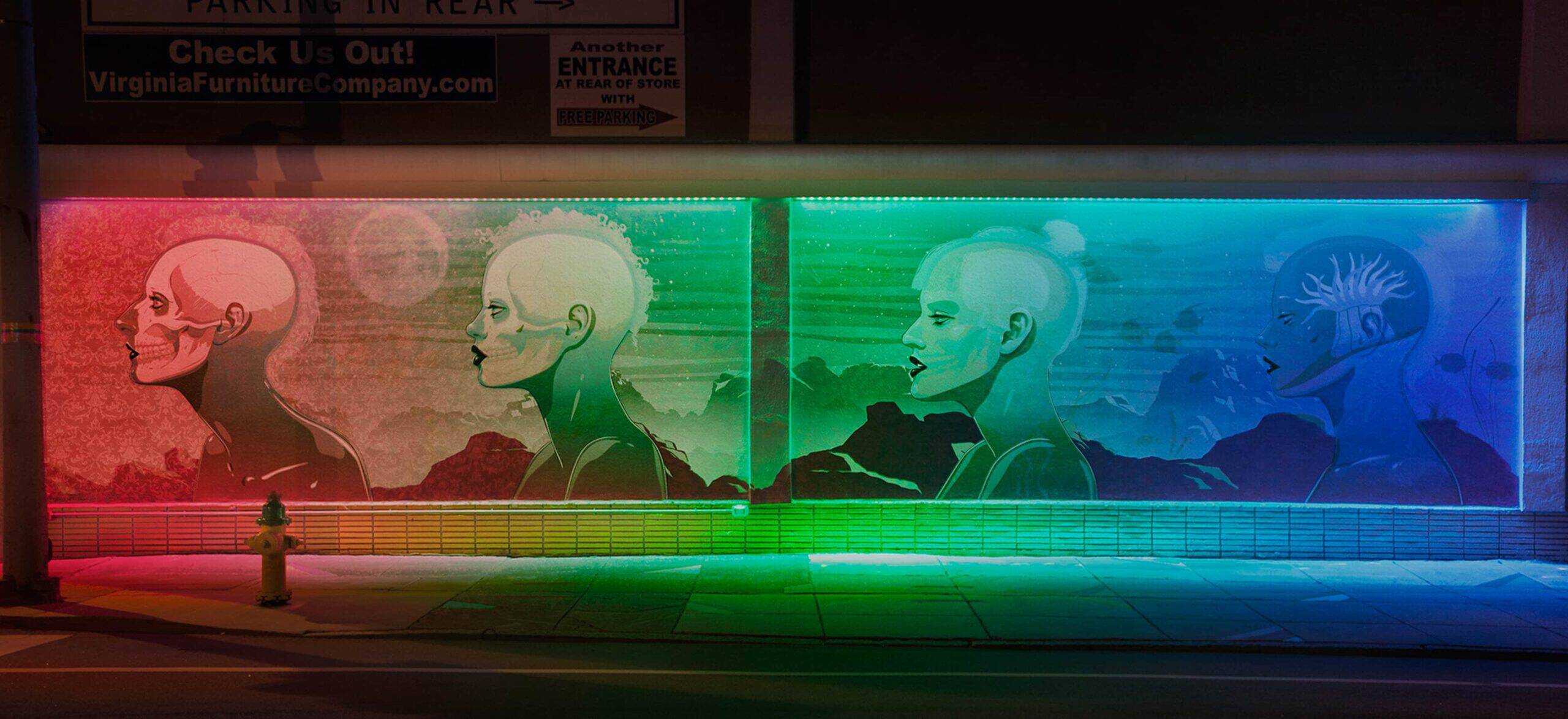
Created in collaboration with renowned artist Jason Levesque, the 40’ installation is located in Norfolk’s NEON Arts District, where color and light are brightening a once-overlooked neighborhood. We’ve shared some background on the project from a conceptual and creative angle, but wanted to dive deep into the technical details that make the work actually work.
Prototype
Sensing Solutions
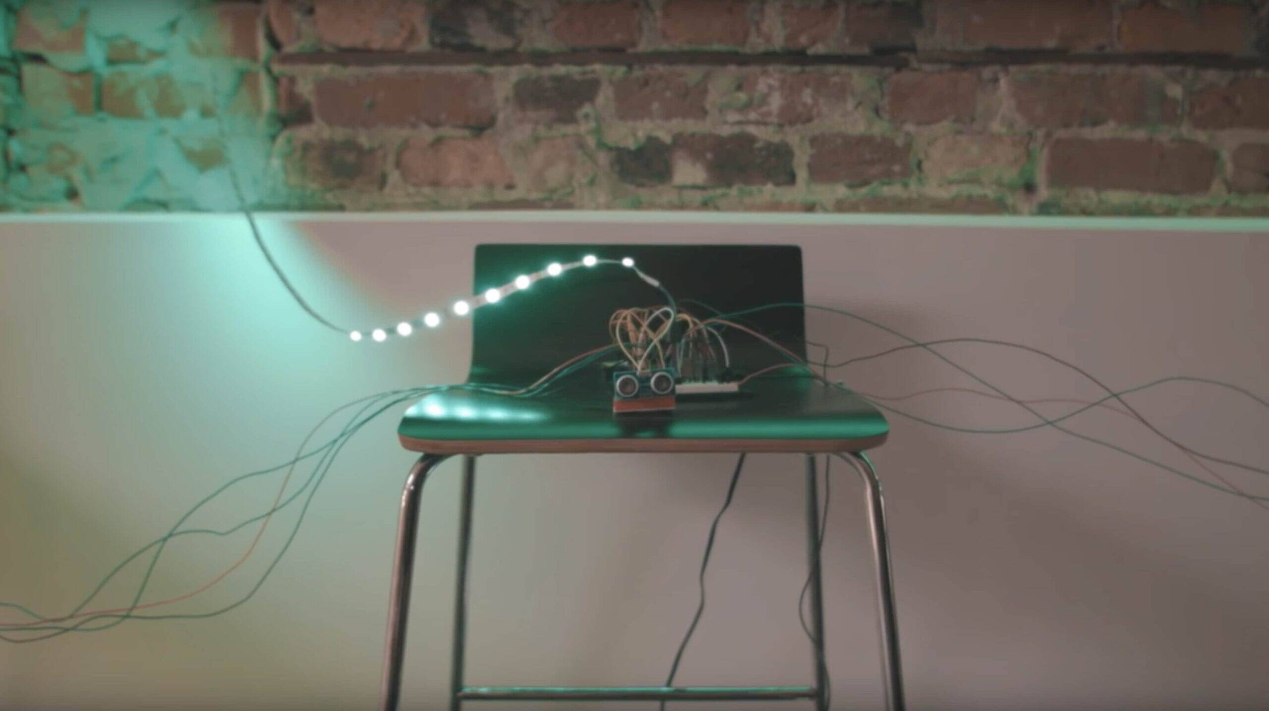
Throughout the project, we explored several solutions to track people as they moved across the mural. We started with ultrasonic sensors connected to an Arduino. We then evaluated using a Microsoft Kinect 2 before settling on a pair of FLIR thermal cameras.
Ultrasonic Sensors
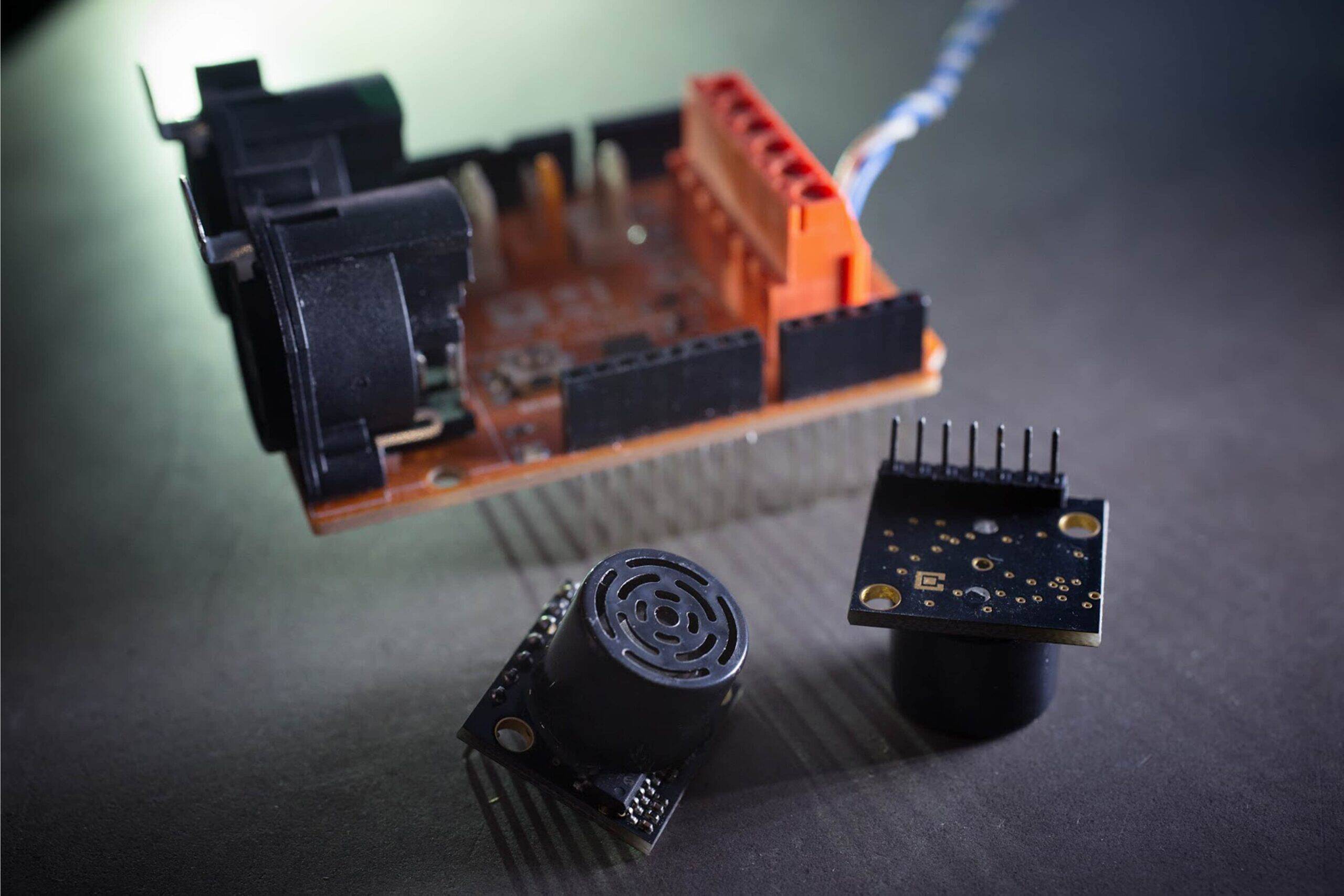
An ultrasonic sensor determines the distance of an object in front of it based on the time it takes for a ping to be echoed back to it. Distance can be calculated by multiplying the speed of sound by the amount of time it took for the ping to return to the sensor.
Ultrasonic sensors are great because they are inexpensive and generally easy to work with. The downside of ultrasonic sensors is that one ping can be picked up by several sensors. Other noise in the environment can also trigger the sensor. With only one sensor, this generally is not a concern, but noise became an issue for us when dealing with 40 sensors. We tried various means of noise reduction, but no approach really solved for our false positives.
Another downside to ultrasonic sensors is that you only have one-dimensional information about an object’s position. Depth is known, but not lateral position. This caused occasional flickering when the edge of an object entered a sensor’s detection zone and left again quickly. It was possible to eliminate most of this noise with additional polling, but that fix introduced latency issues.
Kinect
The Kinect and Kinect 2 from Microsoft are common sights in computer vision research. They offer RGB and IR cameras as well as depth information and skeletal classification. Depth tracking proved to be quick and reliable. Skeletal tracking worked well, but not for our application because of distance limitations and latency in initial detection.
Currently, it is only possible to use one Kinect 2 per computer. Because of the length of the mural, we estimated we would need at least four Kinects. This would mean connecting four or more computers together to report sensor information to a central source responsible for aggregating results and controlling lighting. We ultimately ruled out the Kinect because of the difficulty in connecting multiple units together, and the growing level of complexity for this solution was deemed to be too high.
RGB Camera
We also evaluated using traditional RGB cameras. While they are relatively inexpensive and easy to use, the only data to work with are the shape edges that can be extracted from each frame. Noise from the background has to be filtered out of this data. Using an RGB camera would not have been impossible, but the level of effort required to bring it up to acceptable accuracy was infeasible.
Thermal Camera
In the end, we chose to use two thermal cameras from FLIR. Thermal cameras capture infrared radiation to form an image. This helps make detecting people easier than with a traditional camera, where all you have to go on are edges and shapes.
The advantage of thermal cameras is that heat signatures can be easily detected and extracted programmatically, against a static background. The downside–in our case–was that the temperature of the background in our application (the sidewalk) varied depending on weather conditions and the time of day. In addition to this, peoples’ heat signatures varied depending on clothing. With a lot of testing, from recording in walk-in freezers to turning the heat up to 90 degrees, we were able to create filters that worked in all temperature ranges and adjusted for people dressed in winter or summer attire. We were even able to achieve good results for people holding umbrellas.
Hardware
Over the course of the project, we experimented with a few different platforms as we explored sensing solutions. We started the project using an Arduino Mega. After switching from ultrasonic sensors to a camera based solution, we started developing on a Windows PC as Kinect 2 support on Linux and Mac was poor. Finally, after switching away from the Kinect to thermal cameras, we were able to migrate the system to run on a single Mac Mini.
For lights, we chose to use Philips ColorGraze lights from their Color Kinetics line. The units are designed to be used for outdoor architectural lighting and can be controlled over DMX through a proprietary Data Enabler. The units we purchased were four feet long and controllable in one-foot increments. On the Arduino, we used a DMX shield to connect directly to the lights. On PC and Mac, we used an Entec DMX USB Pro.
Each thermal camera was mounted approximately 25 feet above the sidewalk and fed into a multiplexer. The multiplexer interfaced with the computer via a USB analog to digital converter (ADC).
Throughout all of these platform changes, most of the C++ codebase stayed the same. While the nuances of lighting zones and the handling of sensors changed, the core framework was ported easily from device to device.
Software

The computer vision portion of the application uses OpenCV, an open source computer vision library initially developed by Intel. We used it to process thermal imagery and extract points of interest. A frame of video captured from the thermal cameras was cropped, resized, and converted to grayscale. The image was then fed into a built-in canny edge detector resulting in a list of contours. Small contours were thrown out and nearby contours were merged together. If the resulting image fit our criteria for size and shape, a bounding rectangle containing the contour was added to a list of hits.
From this list of matching objects, the center-point was established for each contour. Because of the angle and field of view of the cameras, objects on the sides had to be adjusted toward the center of the detecting camera’s field of view.
The points of interest were passed back to the main controller for the mural and the state of each active zone was updated. In order to prevent flickering when a person is near the edge of two zones, a warmup and cooldown period were implemented before state changes are reflected in the lights.
In an inactive state, the lights toggled between two presets. When a person stepped into the mural, the zones around a person would turn to the active color with the remaining zones changing to the inactive color. Color choices picked from a static pattern. An internal clock maintained transition times when switching between different patterns and colors.
Conclusion
After all this exploration and prototyping, we were finally able to bring the mural to life on the corner of Granby St & W Olney Rd in Norfolk’s NEON arts district.
The project launched with plenty of local fanfare and drew attention to the budding new NEON Arts District, when it was picked up by The Creator’s Project, Fubiz Media and regionally in RVA Mag. It quickly became the most widely shared piece of social media content Grow has ever produced, and the IRL work continues to attract curious locals and visitors to Norfolk’s newest neighborhood.